This photo shows the pedestal with the cranks and pedals. Inside the pedestal are pulleys and a belt The lower pulley connects to a drive shaft that runs inside the carbon tube shown on the cockpit floor. That shaft connects to the second part of the system, the leg, which rotates laterally to swing clear of the water.
As you can see, the top of the pedestal is being used as a sheeting base. A central sheeting base was needed and will be very helpful in keeping the boat on it's feet.
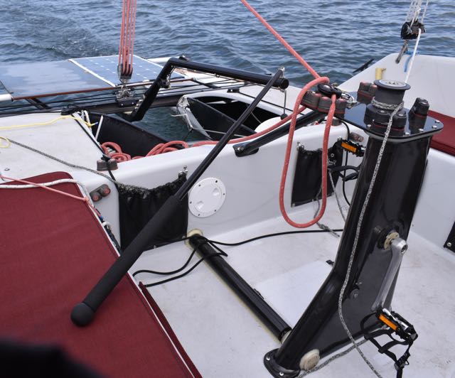
The leg (on the right) also has pulleys and a belt inside and a fairing and bracket on the outside.
Both ends of the leg are capped and a seal on the prop shaft keeps water out of the leg.
The leg rotates sideways (to port) to kick up clear of the water and is controlled with 2 lines.

The bearing retainers were made from thick G-10 fiberglass plate. These are the lower retainers on the leg and the only ones that were bolted on (in case belt tension adjustment was needed), instead of being bonded in place like the other 6 round retainers.
The thin round plate screwed to the retainer is holding the bearing in place and (believe it or not) there's an o-ring notched into the hole that the shaft goes through which, so far, keeps the water out of the leg.

Both ends of the leg are capped with a thin piece of fiberglass plate held in place with a tiny bead of 5200. The bottom face of the fairing is capped as well, but the fairing fills with water in use.

Looking inside the pedestal from the bottom, there's a 60 tooth pulley at the crank shaft and a 14 tooth pulley at the bottom with an idler pulley (for adjustment) in between. The idler was a mistake. I should have designed the pedestal around a stock belt length without an idler. The idler is complicated and a power loss.
Note the squared-off shaft at the upper right. That connects to the shaft that runs between the two units (see below).

Yes, those are 1/2" drive socket extensions. The shafts were squared with a grinder, fiberglass was wrapped around the shafts, and they were cut off and then turned on the lathe to fit (& glue) into the scrap carbon tube that I used as a drive shaft. The drive shaft is 44" long.

The pedestal was built using scrap carbon tube split in half for the edges and flat cored panels to make the walls. The seams were taped inside and the exterior was covered with a couple of layers of carbon.

The leg was laminated on a hand-shaped, tapered, and teflon covered mandrel.
The laminate was a mix of unidirectional and braided carbon sleeve done in 3 separate vacuum bagging steps.

The carbon tube that supports the leg and houses the drive shaft was a reject carbon tube (too fat) from one of our nesting dinghy masts. The fiberglass sleeve that the bracket was molded around is a socket from one of our dinghy kits.
The final weight tally of the finished parts is 18.5 pounds. The metal parts count is big: 5 pulleys (the big one weighs 2 pounds), 5 shafts (including the crank and prop shafts) machined from 16 mm titanium, 10 bearings & retainers, 1 long drive shaft, cranks & pedals, etc...
This was a very complex project and only came to fruition with a large amount of help from Paul Zeusche and Rick Willoughby. The results so far seem very good.
Video at: https://www.youtube.com/watch?v=8C8yd76OY6Q

Nice work - what prop did you use?
ReplyDeleteYou mentioned your knees hurting, I'm guessing part of that is that your legs aren't extended enough. At least that's what it looks like in that video. I ride a lot, and if my seat is 1/2" too low my knees start screaming almost immediately.
ReplyDeleteGreat results and very nice drive system.
P.S: This is Trevor.
DeleteBeautiful workmanship as usual. You mentioned your new system as 60/14 which is 4.28 to 1 ratio, do you know the ratio of your 2017 system? Thanks Russell and again beautiful work.
ReplyDeleteok found it, 73/13 pulleys. Pedal drive developing is very interesting indeed. Later, roger
Delete