Wednesday, August 15, 2018

Pedal drives on 2018 R2AK boats

Here are photos of some pedal drive units that caught my eye in the 2018 R2AK.
This post is a bit short on the technical side because there wasn't time for those kind of questions, but I'll update the post if anyone wants to contribute.

Every competitor's pedal drive system got worked hard this year because there just wasn't much wind, so it was a good year to learn about them.

My pedal drive system worked beautifully in the R2AK, thanks to lots of design help and a good machinist (see previous post)  There were much simpler systems on other boats that seemed to work fine too.

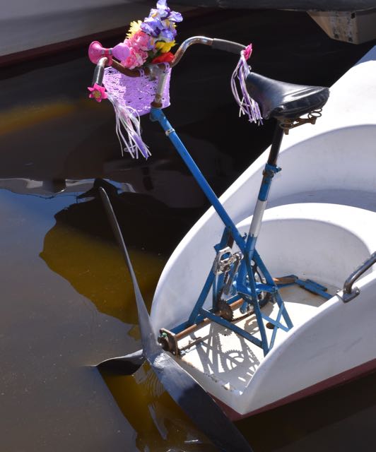
The system below was my favorite, not because of the basket and flowers, but because it was so simple and it worked.
The gearing was timed so that each pedal stroke would equal one propeller blade entering and exiting the water.
The surface-piercing propeller has been used for pushing big boats with human power before (on "Bad Kitty" last year, for example) and the lack of complexity is appealing.
This system was on "Take me to the Poolroom", which finished fifth.


Another extremely simple system was this on an F-28. When I saw this I was doubtful that it would hold up. It did. In fact both of them did (one on each side) and the crew said that they worked well.
The exposed chain would cause drag for sure, but a fairing could be used. The boat also had rowing stations.


The Nacra Inter 20 had twin pedal drive stations rotating forward (to kick up) on the same cross bar.
I don't know about the innards, but it looks like gears and a drive shaft.
This boat was doing well the first day, but didn't continue.


Sail like a Girl had store bought units with seats attached. These were Wave Walker units that use a twisted chain (I believe) and I was impressed that these units were still working at the finish because pushing a pedal powered kayak is quite different from pushing a big sailboat long distance.
The delivery crew for the return trip said that they were not working a week or so after the race.
This boat had four people prying her through the water whenever the speed dropped below 4 knots, two on the pedals and two on stand-up paddles.
Sail like a Girl won this year's R2AK out of determination and a lot of pedaling and paddling.


This system on Wild Card seemed like it pushed the boat really well. There was only one unit and no rowing stations and they finished third. I never found out what is inside the leg, but my guess is right-angle gears and a drive shaft.

My drive unit from last year was on the Olson 30 Dreamcatcher. It got modified a lot at the upper end to allow facing aft instead of facing sideways and it was still going strong at the end of the race.


My 2018 drive system may have been the most complicated, but it deployed and retracted easily, it was quiet, and it was easy to use with the sails assisting. My speed without any wind was 2 1/2 to 3 knots, but I could motor sail up to about 5 knots.
I started with a 16" diameter x 16 pitch propeller, but bought a giant 20" x 18 pitch and cut the tips off to make it about 17" diameter. That prop was to be used just for motor sailing, but it stayed on the whole way. Rpm's at the cranks were about 65 at cruising speed.
The leg never leaked a drop (through the prop shaft or anywhere else), so the belt and aluminum pulleys stayed dry.
My knees got totally hammered from pedaling. Why? Was it the uneven cranking revolutions inherent in most of these systems (cranks and propeller slowing between pedal strokes)?


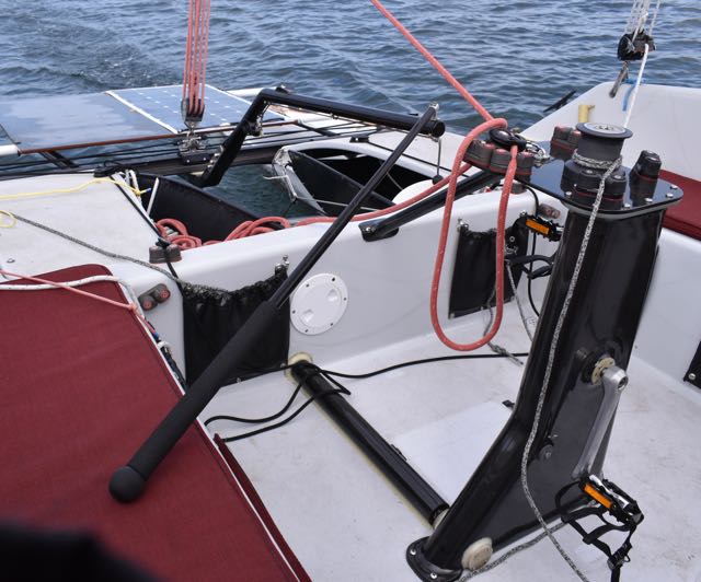
I'm pretty sure that the most efficient drive system was on this boat, Mat Johnson's "Take me to the Volcano".
Matt is facing backwards in this photo. Just behind him are the cranks, pedals and bicycle style gearing and a short shaft that runs to a 90 degree gearbox at the hull side. The gearbox is angled downward to force the long spring stainless propeller shaft (visible in the photo) down into the water.
The thin aluminum strut at the propeller rotates sideways to lift the prop and shaft clear of the water.

This system was designed by Rick Willoughby. Here's an example of the kind of power a system like this can generate: https://www.youtube.com/watch?v=0JH5wx-4OoI


What will we see next year? Will someone develop a production leg (lower unit) that can be adapted to different boats? Will surface piercing propellers become more widely used? What about flywheels to even out the rpm's?
Pedal drives can mess with your head. Every system is a combination of compromise and complexity, but there are worse things, I guess.


This photo courtesy Katrina Zoe Norbom


Friday, May 25, 2018

pedal drive

I finally got the new pedal drive system working and it seems really good. It's a bit hard to show, because it's comprised of two separate parts that are about 4 feet apart. The part with the pedals sticks up and the part with the propeller points down. See video at:  https://www.youtube.com/watch?v=8C8yd76OY6Q
This photo shows the pedestal with the cranks and pedals. Inside the pedestal are pulleys and a belt The lower pulley connects to a drive shaft that runs inside the carbon tube shown on the cockpit floor.  That shaft connects to the second part of the system, the leg, which rotates laterally to swing clear of the water.
As you can see, the top of the pedestal is being used as a sheeting base. A central sheeting base was needed and will be very helpful in keeping the boat on it's feet.


The leg (on the right) also has pulleys and a belt inside and a fairing and bracket on the outside.
Both ends of the leg are capped and a seal on the prop shaft keeps water out of the leg.

The leg rotates sideways (to port) to kick up clear of the water and is controlled with 2 lines.


The bearing retainers were made from thick G-10 fiberglass plate. These are the lower retainers on the leg and the only ones that were bolted on (in case belt tension adjustment was needed), instead of being bonded in place like the other 6 round retainers.
The thin round plate screwed to the retainer is holding the bearing in place and (believe it or not) there's an o-ring notched into the hole that the shaft goes through which, so far, keeps the water out of the leg.


Both ends of the leg are capped with a thin piece of fiberglass plate held in place with a tiny bead of 5200. The bottom face of the fairing is capped as well, but the fairing fills with water in use.


Looking inside the pedestal from the bottom, there's a 60 tooth pulley at the crank shaft and a 14 tooth pulley at the bottom with an idler pulley (for adjustment) in between. The idler was a mistake. I should have designed the pedestal around a stock belt length without an idler. The idler is complicated and a power loss.
Note the squared-off shaft at the upper right. That connects to the shaft that runs between the two units (see below).


Yes, those are 1/2" drive socket extensions. The shafts were squared with a grinder, fiberglass was wrapped around the shafts, and they were cut off and then turned on the lathe to fit (& glue) into the scrap carbon tube that I used as a drive shaft. The drive shaft is 44" long.


The pedestal was built using scrap carbon tube split in half for the edges and flat cored panels to make the walls. The seams were taped inside and the exterior was covered with a couple of layers of carbon.


The leg was laminated on a hand-shaped, tapered, and teflon covered mandrel.
The laminate was a mix of unidirectional and braided carbon sleeve done in 3 separate vacuum bagging steps.


The carbon tube that supports the leg and houses the drive shaft was a reject carbon tube (too fat) from one of our nesting dinghy masts. The fiberglass sleeve that the bracket was molded around is a socket from one of our dinghy kits.

The final weight tally of the finished parts is 18.5 pounds. The metal parts count is big: 5 pulleys (the big one weighs 2 pounds), 5 shafts (including the crank and prop shafts) machined from 16 mm titanium, 10 bearings & retainers, 1 long drive shaft, cranks & pedals, etc...

This was a very complex project and only came to fruition with a large amount of help from Paul Zeusche and Rick Willoughby. The results so far seem very good.

Video at: https://www.youtube.com/watch?v=8C8yd76OY6Q

Monday, March 26, 2018

Catching up....

Sorry that I let the G-32 blog slide. Things got a bit hectic before the R2AK. getting all the parts to work well enough to go sailing was a bit of a stretch...
I did make it to Ketchikan and the sailing was great! I did have to fix stuff the whole way however.
Following are some photos of rig details, etc.

The hounds fitting (that holds the mast up) and the running backstay fitting (also holds the mast up) were carefully considered.


These parts were cut out of 6061 T6 aluminum on the table saw from stock I had left over from the last hounds fitting I made that were a similar design. The last one now has about 35000 miles on it, so it must be good, right? The reason that these fittings are glossy is that they were coated with WEST SYSTEM G-Flex right after sanding them thoroughly This was to seal the aluminum and isolate them from the carbon mast.  


These fittings are installed from the end of the mast so that the tongue (the outside part) can poke through a slot in the mast. The fittings were installed with epoxy. The oversize holes were filled with epoxy and then fasteners were installed (with epoxy) that were tapped into the aluminum.


The masthead was incredibly complex. The sheave boxes had to be built around the socket for the axle for blimpie.

The sheave boxes were made over a male mold (a piece of wood run through the planer to the right thickness and covered with adhesive-backed teflon).

There are only two halyards (main and screecher/spinnaker) and a topping lift, but it took 4 sheaves to make it all work. Fortunately, one of my first real friends in Port Townsend is now a custom sheave maker. Zephyrwerks.com.


Lots of parts and carbon taping happened between the above and below photos.
The holes in the side of the mast are for installing sheave pins. The holes in the top are for routing halyards.
Barely visible inside the mast is a bulkhead that seals the top of the mast from water entry if the boat is capsized (for added flotation). The bulkhead has very light conduits glued into it that run about 6' down the mast to carry the halyards.


The mast tiller had to be shaped to fold upward for lowering the mast. The last one of these I had made out of stainless tubing and it was heavy and it bent, so this one had to be really strong, but also quick to build.


I made a mold from a solid piece of wood and added plywood flanges. These pieces were covered with plastic tape when separate and then stapled together.


Many layers of unidirectional carbon (cut to just the right width) were wet out on plastic and laid into the channel formed by the flanges and then forced down with two narrow squeegees.


The result was a rectangular section of the shape I wanted.


The section was made almost round on the router table.


Layers of tubular braided carbon were applied to the high load areas. After sanding a layer was applied over the whole part.


This photo shows the mast tiller and also shows the universal joint that the mast sits on. The mast must be able to fold forward for trailering, lean sideways for righting the boat when capsized, and rotate. There are thin teflon disks between the upper aluminum part and the mast and a pin that the mast rotates on.


This photo shows the pin that the mast rotates on. The aluminum parts were modeled with wooden parts made on the table saw and drill press until the geometry seemed to work, then a CAD file was made from measuring the wooden parts and the aluminum parts were CNC cut.
The pins are titanium, which sounds expensive, but it's not when bought in rod or plate stock.


New rudders were built over the winter. Actually a whole new steering system was made, but that's a topic for another blog post. I haven't tried them yet, but they look good.