Thursday, November 10, 2016

Adventures and a misadventure

Well, I had a great weekend of sailing and one very close call. 
Sailing up to the San Juan’s and back was very educational with lots of different wind strengths from every direction. I went there to sail with boats competing in the Round the County race. It is a two day race completely around the San Juan’s, but I was planning to chase the fleet on Saturday and return home Sunday. 
Photos by Sean Trew

I started well behind the last starters for the beat down Rosario Straight. Despite having to avoid the boats racing, I was able to work my way through quite a bit of the fleet. Near the southern end of Lopez Island, the wind really started to blow.
I had been sailing with the reefed mainsail only, but had to keep reefing it deeper as the wind built. 

The boat was comfortable and felt good despite the conditions getting pretty wild (wind around 25 knots and opposing current causing breaking waves). 
The turning point was a large marker on an exposed reef called Davidson Rock. 

I had over stood the tack and had some room from the reef. Once I was able to crack off onto a reach, I slacked the leeward running backstay and rolled out the jib.
There was a loud bang and the boat capsized very quickly. 

It took a while to get a complete picture of what happened, but it was this: The windward running backstay had let go, allowing the mast to pitch way forward.* The mainsail was the only thing limiting the forward movement of the mast and was pulled very tight as a result. The jib stay went slack causing the jib to be very full, like a spinnaker and the combination of the two (and a gust) caused an immediate capsize.

The amazing thing is that the boat didn’t go upside down, even with the masthead float somewhere out over the bows.

The reef (with breaking waves on it) was just downwind and I didn’t know what had happened to the rig. I thought something had broken, but I got the sails mostly furled and found the running backstays to be in working order. 
I was able to right the boat in a few minutes, get the rig back upright and roll out a bit of jib and ease away from the reef.
photo by Sean Trew
What caused the running backstay to release? The line came out of the cleat. Not because it wasn’t fully cleated, but because the plate that the cleat was mounted to deformed under load and caused the lead angle to the cleat to change enough for the line to pull out of the cleat (see photo below). 
This is new hardware, one size bigger than what came with the boat. It’s a six part tackle with a working load of 900 lbs and a breaking load of 1800 lbs.

The tackle that most G-32’s use has a 600 lb working load (this boat has a tiny rig), so why mine failed is a mystery that I’d like to solve.
I am planning changes to the running back stay system and I’m glad that I now know what happens when when there’s a failure in that system. If it ever happens again, I just hope it’s not near a breaking reef.

Short video  HERE.
Note that the plate that the cleat is attached to is bent
Did I get wet? No I didn't. Only your feet and ankles get wet when righting a G-32. I was wearing an ancient, but well maintained Kokatat drysuit that has kept me dry for almost two decades.

*For those that don’t know, the G-32 has fixed shrouds, but instead of being swept back, they are in line with the mast to allow the mast to raise up and down easily when trailering.

I'm building a new rig for my G-32, which I will post about in this blog. I was planning to make it 3' longer than the stock rig, but that is being reconsidered after my wild weekend.

Text video link if above link fails: https://youtu.be/912H94--Xas


Monday, October 17, 2016

Laminated cross arms for a single outrigger motorboat

This has nothing to do with the G-32, but I just built a set of laminated cross arms for a Bieker designed motorboat that seem worthy of a blog post.


The boat is experimental (don't ask about plans) and the parts for it were cut and built in Port Townsend to be shipped to Bermuda where it will be built.
My job was to cut the lumber kit and build the cross arms and crate all the parts for shipping.

The boat will be 20' long and similar to the single outrigger shown in this video starting at about one minute.  https://www.youtube.com/watch?v=HevgDyupZeY

Solid laminated Douglas Fir was chosen was chosen for economy and strength. The beams took about $ 150 in Fir and took around 25 hours to build to the stage shown.

The weights are 16 lbs for the forward beam and 9 lbs for the aft beam. They will be shaped on the forward edges and covered with fiberglass cloth.
The beams are just under 8 feet long and seem very strong.

The laminates were sawn by bandsaw from three 2"x4"x 9' pieces of Fir. The laminates were run through a thickness planer to remove the saw marks.

I cut these laminates quite thin (around 3/16" to avoid too much spring back at the tightly curved outboard ends, but it still took a lot of force to bend all 11 of the laminates around the jig for the forward beam.  I wanted the laminates to be thin enough to bend to the curve in a fairly relaxed state because I thought that the finished beam would be stronger and the glue-up would be easier.

The obvious solution was to taper the laminates, which turned out to be quite easy using the thickness planer.  I was even able to match the taper to the designed taper of the beams which meant that I didn't have to cut the taper after laminating.

My planer ( a fantastic Dewalt 13" portable) won't plane wood less than 1/4" thick without raising the base with a piece of plywood clamped to it, but with that method I was able to feed laminates into the planer and slowly lower the cutter head until contacting the surface with them about halfway through and then slowly cranking the cutter head down to cut taper before raising it up again and repeating, the second time cranking a bit faster to cut more taper.
I was able to run a couple of laminates side by side and had tapered all the inner laminates before clamping the stack to the gluing jig to check the taper against the CNC cut plywood templates that were provided.
In the end I was tapering one or two laminates at a time in marked areas to achieve the designed taper.


The gluing jigs were made by gluing square-cut block to the bench with dabs of 5-minute epoxy before screwing them to the table. The blocks were aligned to a batten while the 5-minute cured. 
The template would have been used to align the blocks, but I slightly softened the curve near the outboard end to make bending the strips easier.
Plastic tape (visible) was applied to the table before the batten and blocks.


After dry runs and fine-tuning the taper, the beam is ready to glue-up.
Slightly thickened epoxy (105 / 206 with colloidal silica and micro fibers) was applied to both faces of each laminate using a short nap roller that was cut to the width of the strips. The nap roller will apply thickened epoxy much faster and more evenly than a foam roller.


The glue-up was a breeze, partly because the laminate stack could bend so easily, and partly because the jig worked so well.

 I used blocks of wood with long lag bolts to hold the laminate stack down tight to the table surface and used blocks under the head of every clamp to spread the clamping pressure

There was very little spring back when the beam was removed from the jig. I did heat the beam for a full epoxy cure (by tenting with electric heat) before removing clamps.


The aft cross arm is a different dimension and a different curve. The blocks were re-used for the new jig by cutting them down on the table saw.


The beams were run through the thickness planer to clean all the squeezed out epoxy from the fore & aft surfaces (using older blades) before rolling on a thin coat of epoxy for protection.


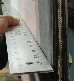
This photo shows the cross sections at either end of the forward beam. The laminates are quite a bit thinner at the outboard end, except for the outer laminates which were not tapered.


Saturday, September 3, 2016

Sailing!

Yes, the boat is sailing, but only because I have been hard at it every day, ignoring my friends, the telephone, our business, my wife, and yes, my blog.


We leave tomorrow on a short cruise as a shake down for a longer trip later in September.
I promise to fill in all the blank spots in the re-construction of the boat and the building of the hatches, etc, and hopefully add some good sailing photos. For now, just these few photos are all I have.
Do I like the boat? Yes I do.


Tuesday, May 10, 2016

Fairing in prep for paint.

Yes, it has been a while since this blog was updated, but I have been suffering through the hell of fairing the boat and didn't really want to talk about it. Now it's all shiny and the plastic tent is gone and my shop is no longer a dusty pit. I still have to paint the boat, but that seems like less of a chore than fairing.


Many parts of the boat had fairly even gelcoat application and the boat was quite fair to begin with, so it could have been much harder. Areas where gelcoat spraying was difficult, the gelcoat was applied with a brush. When it was removed, it left deep ridges and valleys that needed to be filled and sanded multiple times. The cockpit, both sides of the seat backs and aft crossarm were really a chore to fair. The tan and reddish colors in the photo below are areas filled with microlight or low-density fillers.

The fairing started with some careful selective filling along the waterline and where the gelcoat was left under the wing.  
The light shining under the batten edge shows how thick the gelcoat is.

The copper color in the lower part of the photo is the copper/epoxy bottom that was applied in the mold. The light shining through is where the gelcoat used to be. 


Both of these areas had to be carefully filled before applying a thickened coat of epoxy to the surfaces of the hulls.

The gelcoat was faired in with my long, strait, and sharp edged application tool.
This step was done before filling the uneven edge at the waterline.
The waterline (all 105 or so feet of it) was faired in using a wide putty knife, applying pressure only to the edges of the knife.

A heavy "fill coat" was applied to the lower topsides over the still-tacky waterline filler.


All surfaces that had had the gelcoat stripped were thoroughly sanded and fill coated with epoxy and 410 Microlight filler mixed in at almost 50 percent by volume.
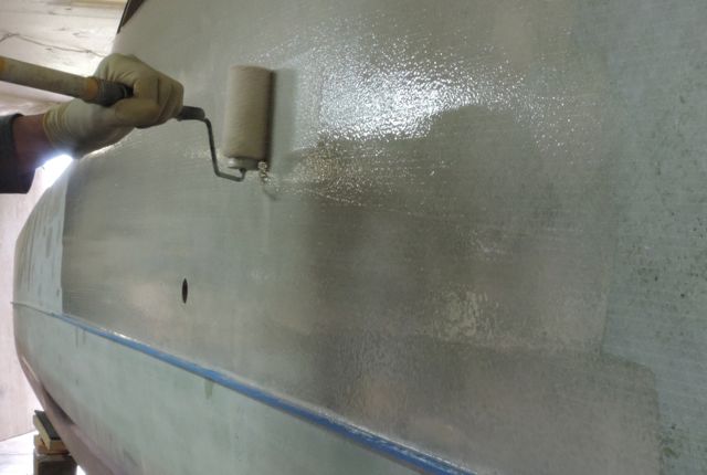
The fill coat was applied with a short (1/4") nap roller.
The nap roller will spread the thick fill coat mix out evenly (with lots of rolling), something that a foam roller can't do.


I used good quality rollers for applying the fill coat. A 9" roller cut in half worked well and was more economical as the rollers soak up a large amount of epoxy.

The fairing process was not pretty and not at all photogenic, I used mostly longboards with 80 and 100 grit for fairing and smaller plywood sanding blocks of varying thickness and stiffness for fairing really curved areas.
The method of rolling on a thick fill coat worked beautifully. The 410 microlight filler combined with WEST 207 hardener made for a fill coat that was both thick and easy to sand. This combination of ingredients seems to somehow flow out fairly smooth, even though it is applied thickly with a nap roller.

When fairing, the low spots remain easily visible as they are semi-glossy (unlike when fairing high-build primer). Low spots were filled and the surfaces sanded again.
I used multiple different knifes for applying thickened epoxy to low areas, from a 12" wide drywall knife to a 3" wide thin putty knife. All knives had sharp & straight edges.

Early on I realized that for me to get the boat sailing, I needed to lower my standards. I skipped steps that really should have been done to make the surfaces more fair or more ready for paint. That being said, what I did was pretty efficient time-wise.

I rolled (and tipped with wide foam brushes) a coat of 105/207 over the entire boat after fairing and this coat will be lightly sanded before paint. No primer will be used.

A gloss coat of epoxy has many advantages over epoxy primer. It "flows out" to make a smoother membrane and because it is glossy, you can see imperfections that may need more work before painting. Most epoxy primers stink for days after application and, while primer is softer for sanding, one is sure to sand through it in places, so there is no solid color advantage to using primer. Primer is also softer that two-part paints, so using epoxy instead of primer may make for a tougher paint job.


Like sanding the fill coat, sanding the glossy epoxy coat is made easier because it is glossy. It's easy to sand just enough for the glossy spots to disappear, without sanding through the gloss coat.
I had some seams in the gloss coat (because I broke the surface into different sections for coating) and even though I tried to thin the coating at these taped edges, the seams were still difficult to sand flat.
I use a thin flexible fiberglass plate sanding block for areas like this, using 220 grit sandpaper, which is appropriate for 2-part paints (photo below).

Most finish sanding is done with  a random-orbit sander. For edges and corners, a hard rubber sanding block and a foam rubber sanding block, all with 220 grit. Remaining glossy spots are hit quickly with a 3-M abrasive pad.

I have finally started painting and it is going well, even with two large exhaust fans pulling dust through my shop. Better some dust in the paint than to absorb nasty fumes.
We are taking painting photos in order to update our book "Rolling perfection", an e-book we sell about using Interlux "Perfection", a two-part LP paint.


I built a honeycomb & fiberglass hatch for the cabin. It's compound curved to fit the cabin and has a gasket notch machined into the edge.

The hatch is made from honeycomb with fiberglass skins so that it can let light into the cabin.
My previous boat had a honeycomb and glass companionway drop board and the light it let in was not only welcome but quite beautiful as well. Hard to show in a photo...

The hinges were made in a long blank from G-10 plate and G-10 tubing that were glued together before bagging carbon over the length of the blank.
I took careful photos of building the hatch and hinges and may do a blog post about it if there's interest.

The molded in rudder gudgeons had carbon reinforcement (this was visible without the gelcoat), but I did some reinforcement and clean-up anyway.
The holes for the pin were a bit sloppy, but it was super easy to remedy that, thanks to aluminum's thermal expansion.
The holes were drilled out to a larger diameter and opened up a bit at the upper ends to allow epoxy to enter. 3/8" hardware store aluminum tubing was waxed and inserted. Vacuum bagging mastic was used to seal the lower ends of the holes as shown before heating both upper and lower gudgeons with drop lights.  Epoxy was syringed in and because of the temperature, quickly flowed in to fill the void around the tube.
The drop lights were kept aimed at the gudgeons until the epoxy had fully cured. After cooling, the aluminum tubes pulled out easily by hand.


Thursday, February 25, 2016

Gelcoat Chippin'

The gelcoat is finally off and was hauled to the dump today as a matter of fact. We didn't remove the gelcoat from the underwing (last photo), but it's off all other areas except for the forward beam, where it seems to be stuck quite well.
Was it a good idea to strip the gelcoat? It seemed like a good idea at the time. It was coming off easily in areas and I couldn't see patching in areas with epoxy only to have it start coming off somewhere else. The reality is that the gelcoat was adhered reasonably well in most areas and very well in others. Of course, there were some areas where it just fell off, but the final tally was only 70 lbs of gelcoat removed. Considering the work involved, 70 pounds doesn't seem like much. When I say work involved, I'm only halfway there, as the the boat still needs to be faired and painted.


Gelcoat removal never would have happened without a little help from my friends. Alex Spear got it all started just by stopping by for an hour or so every few days.

We quickly learned that warming the area with a heat gun set on low really helped. I bought 3 heat guns.

There may be a miracle method for removing gelcoat, but I don't know what it is. We used sharp chisels and heat. All of the chisels got noticeably shorter from sharpening, even my high grade Japanese chisels.


I think this means ours is the 9th G-32, even though the sail number is 10.
I have a gimpy wrist, so I added a very long handle to my favorite chisel so I could use both hands.

The heat gun is strapped to my forearm with an elastic bandage.
There's a foam pad in there to angle the gun up and just the right number of wraps this way and that to aim it in the right direction.
Most of the large areas came off with this goofy set-up.
The gelcoat stuck well to the copper/epoxy near the waterline.
I chipped from above to get down to the waterline. Pushing back and forth on the handle gave a slow controlled pace until the chisel stopped at the copper/epoxy edge.

Chuck Hosmer just chipped off the very last piece of gelcoat, that's why he looks so happy.

Chuck bought this G-32 new in 1992 and has taken good care of it until I bought it last year.


This is what 70 pounds of gelcoat chips looks like. Did we catch all of it? No, this stuff really flies when it chips off. All of the shop shelves have gelcoat chips on them, even using plastic curtains. I'm sure that some of the kits we have shipped had a chip or two in them.
At least we didn't have to grind the stuff off. No Dust is good dust.


The remaining gelcoat can be seen below. It's an area about 12 feet long x 7 feet wide. It isn't stuck particularly well there, it's just hard to get at because my ceiling is so low.
The dolly I have been using to move the boat around the shop can be seen here. The cross-pieces are made from very strong Fir 2x10's with 600 pound casters set inboard of the hulls so that the flexing of the 2x10 make up for the uneven floor (to keep from wracking the boat).
The long fore & aft blocks spread out the load on the hulls and are placed where the watertight bulkheads are located. When jacking the boat up or down, the whole assembly is tied to the hulls to keep it from moving (see next photo).


I have been lifting the boat up and down with a screw jack from my truck (that's what the yellow cordless drill is attached to).  Lifting on center means that the boat can be blocked up relaxed (not twisted), but the underwing at the fwd end is not supported, so I use a long padded 2x10 to spread the load.


Tuesday, February 16, 2016

Straighter and stronger stems

 The bows on my G-32 had two issues that I wanted to remedy; they were misaligned and they were delicate.
The misalignment wouldn't bother anyone but me, but the rest of the boat is so beautifully fair and I didn't want to look at crooked stems.

The delicate part probably wouldn't bother anyone not sailing in the North West where floating logs are a menace, but I do sail here and this boat has plumb stems, so there's little chance of riding over a log.

In the G-32, the core stops about 2' back from the stems and it's solid laminate foreword of that, which is all good, but in my boat the laminating must have been done on a friday, because it was very thin in some areas and not thin in others.
In the builder's defense, it would have been very difficult working in the stem areas of these molds.

So, I wanted the stems to be stronger and I wanted them straighter and I got both with the help of wood, carbon, glass & epoxy.

 From a cardboard template I cut hard mahogany caps and glued them to the front edge of the stems


A long and stiff sanding block (with 40 grit paper at one end only) was used to bevel the stem caps to the plane of the hull surfaces.
This step was where the straightening of the stems happened. Compare to the photo above.


The new stem is obviously thicker than the old, so thickened epoxy was applied to fair the thicker stem into the rest of the hull.
Yes, this added weight, (I used over a quart of epoxy for fairing), but the filler had a benefit:  A layer of glass cloth was applied over the whole area as a final step  and that, with the filler acting as a core, made these areas of the hull very stiff.


Because the areas being faired were still flexible, the filler had to be applied carefully. Sanding a flexible area with a longboard doesn't really work. The flexible parts  yield and the firm part's don't, so only the firm areas would be abraded and unfairness would result.


Lot's of thickened epoxy was applied and then was carefully tooled or "swept" with a very stiff and sharp edged tool.


The tool in this case is a strip of cored panel that had one edge cut to 45 degrees on the table saw.
A straight and sharp edge is necessary and when using a strip of cored panel, one of the skins becomes the sharp edge.


I swept all areas a second time. The second pass is easier as there's less volume and the epoxy can be mixed thinner.
I did both on the same day for a good bond.


I did a bit of sanding and shaping, then scribed a centerline on the front edge of the stem cap.


The stems were 5 sided and then rounded as shown using a block plane and both stiff and flexible sanding blocks.


 I wanted these stems to be strong. Did I say that?
A good whack of carbon seemed like a good idea.

The problem with laminating a bunch of fiber around the stems is thickness buildup, which means applying more filler to the sides.
To get lots of fiber without lots of thickness we had to vacuum bag the carbon.

The carbon shown is 9 oz (300 gsm) biaxial, which was quite conformable. We applied one layer as shown and another 4" wide strip that can be seen in photos below.

The bleed stack (that's what it's called) consists of a layer of peel ply, a layer of perforated film, and two layers of breather (fuzzy blanket material).

These layers were lightly glued together with spray adhesive in a big sheet and the parts shown were pre-cut from cardboard templates and placed on the wet carbon.


The Vacuum bags were large rectangles with mastic applied to all 4 edges and pre-applied to the boat on one edge only. When the time came, I folded the bag around the stem, attached the other edge and then did the top and bottom edges. The corners of the bag were folded back as shown to allow working out potential wrinkles.

As you can see, nothing but the bag went over the sharp edges of the stem.This allowed visual inspection for wrinkles, where wrinkles would form. As vacuum Pressure was building, I pushed back hard on the bag as shown to move the laminate away and tighten the laminate around the corner.

The laminate looked fine when the bags came off. No wrinkles and little thickness buildup.


The thickness buildup can be seen here and the
remedy (another pass with the sharp-edged stiff & straight tool) can be seen below.

Thickness of vacuum bagged laminate can be figured quite easily if you speak metric.
Fot every 100 gsm (grams per square meter) of fabric, there is .1 millimeter of thickness.
I used 2 layers of 300 gsm fabric and had .6 of one millimeter of thickness buildup (not very much).

5.7 ounce (200 gsm) is the most commonly used carbon cloth. It takes 5 layers to make 1 millimeter of thickness.


The reason the carbon laminate extends so far onto the upper part of the hulls is that we wanted to replace the stainless U-bolts that were in this location with fiberglass tubes that run right through the hull. The holes were cut with a hole saw and the tubes were carefully bonded in with epoxy.


After a bit more sanding, the foreward  26" of the hulls are glassed with 8.9 oz  "Rutan" cloth. We did this one side at a time, (the opposite side done the following day) wrapping the glass around the stems each time.

The glass cloth pieces were rolled onto a length of cardboard tube when flat on the bench, which allowed rolling them onto the wet (with epoxy) vertical hull sides in a controlled, wrinkle-free way.


 The excess cloth was trimmed with scissors to allow just enough cloth to wrap around the sharp edges.
This cloth was wet out around the edges (with the roller) and then held in place with small squares of light peel ply as shown below.


For this to work, a light film of epoxy was rolled onto the opposite side near the edges for the peel ply to stick into and the peel ply pieces are stretched around the corners, making the glass behave like it wouldn't otherwise and making sanding the edges later a breeze.

I also added strips of peel ply to the aft edges to smooth the cloth into the the hull.


Yes, I had to sweep the whole thing one more time with the long straight thing.
I was able to do this the same day, so this was like the fill coat and fairing all in one. I always like for things to be fair without too much sanding... Don't know why.


The G-32 has a copper/epoxy bottom that was applied in the molds. Under the wing deck where there's no sun exposure, this copper bottom is still shiny and smooth. Everywhere else it is oxidized  and green, but a light sanding and polishing makes it look like a shiny penny again.

We had to re apply copper/epoxy to the bow areas, which was easy, just mix the copper powder into the epoxy (lots of it) and roll it on. I warmed the areas with a heat gun while I was rolling and then tipped with a wide foam brush.

I don't know where to buy this stuff, but I asked Tom Pawlak, my favorite tech advisor at Gougeon and he sent me a small can that had been gathering dust on his shelf for decades.


The "Rutan" cloth we mentioned above  is a type we use a lot of and sell with our kits.
Hexcel 7725 is a glass cloth developed with the help of Burt Rutan for his composite aircraft. The fibers are very fine and lay relatively flat (2x2 twill weave).
While it is a bit different to work with than regular cloth, this stuff is very strong for it's weight and thickness and takes less epoxy than comparable weights of cloth.

There is a unidirectional version as well (7715) and both are available in cut lengths from Aircraft Spruce & specialty.