Sunday, January 1, 2017

New rig and other parts.

Well, I'm building a new rig for the G-32 and many other small parts as well. Of course I'm way behind on the blog, but that's the way it seems to go..

Designing the new rig and sail plan was done with help and advice from a number of people and took some time to accomplish. I started in the Fall working on things that weren't likely to change with changes in the rig design.

The spreaders were pretty easy to determine. They are short because they need to fit inside the fixed shrouds and they need to fit the mast section that I will be using.

I had thought to make hollow carbon spreaders, but instead shaped Sitka Spruce blanks and covered them with woven carbon.
My goal with the new rig is to make it as light as possible and to make it as aerodynamically
clean as possible. These spreaders will operate at high angles of attack because the boat heels so much, so I wanted a short chord length for as much of the span as possible.
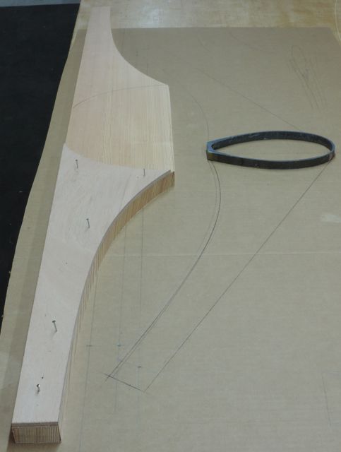


The Spruce blanks were shaped with a grinder, block plane, and sanding blocks. The trailing edge had a solid epoxy fill applied before final shaping.
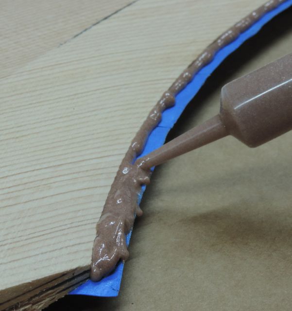


After more shaping, the ends had solid epoxy tips added before the final shaping shown below.


The spreaders were covered with three layers of 5.7 oz, (200 gsm) woven carbon, one of the layers being cut on the bias.
Pulling down hard on the bleed stack to prevent wrinkles at the leading edge when vacuum bagging.


After trimming the edges and sanding, the spreaders were cut away from the center of the blank. Notches were cut in the tips for the diamond wires to run through and holes drilled for seizing.
It shouldn't be long before the spreaders are bonded and taped onto the mast.


The G-32 storage boxes (behind the cockpit) were beautifully designed and quite light, but the hinged lids were right were I wanted to put hardware. The autopilot mount, traveller controls, and other things would like to be mounted right where the lids are.


So I built cored panels similar to the top surface of the boxes.
For storage, there will be mesh fabric bags underneath the panels supported by tent pole-like fiberglass tubes.


I knew that these panels had to be light, which meant they had to be cored, but I didn't want another mold to take to the dump, so I decided to use 3 mm Okoume plywood skins and use the lower skin as the mold surface.

Only the materials shown in this photo were discarded after making the panels.


The lower plywood skin was attached to the framework with double-sided tape (the type sail makers use) and a bit of hot-melt glue around the edges.
A light coat of epoxy was applied to the under side of the plywood first to prevent grain tear-out when removing the mold frames


To use the lower skin as a mold, it had to be completely airtight, so I applied two coats of epoxy, the first being squeegeed into the grain. The second coat was healthy and thorough and was lightly sanded after curing.
The core and top skin are shown here, the core being 5 pound foam (of two different colors).
The core and the top skin have corresponding holes to let air and extra epoxy pass into the bleed stack.


I was able to stretch the vacuum bag tight enough to pull the panel close to the mold surface before turning on the pump, keeping the peel ply and vacuum bag from creeping under the panel edges.


The panel was easily removed from the mold frames and cut into the final shapes using a template, skill saw, and jigsaw.
 
                                                                              Light carbon fiber cloth was applied to both sides and an extra tape was applied around the edges.


Carbon angles were bonded and taped to the aft edges of the platforms. These angles will be bolted to plates that attach to the traveller. 


Carbon angle will also be used to attach the forward ends to the cockpit area.

I needed a lot of angle, so I made a simple mold from plywood with a small bondo fillet in the corner and covered the mold with plastic tape.

10 layers of 400 gsm (almost 12 oz.) woven carbon produced a laminate 4 mm (almost 3/16") thick. 
It's easy to plan thickness with vacuum bagged carbon; each 100 gsm of laminate equals .1 millimeter of thickness.


A new mast head float is underway. It's slightly smaller than the old one and shaped differently. I had a mold machined from styrofoam which was faired, glassed, fill coated, faired again, and then gloss coated.
More on this later...


The mast is an Omohundro section built for the F-25. I bought two of them ages ago that were discounted seconds because there were flaws in the bolt rope track flanges. I built a rig from one of them at least 15 years ago and have been hanging on to the other ever since. The section is heavier than necessary, but I'll be able to have less rigging than the stock G-32 and the rig should still be lighter, even though it's a bit longer. The bare tube shown weighs 48 pounds, the G-32 rig weighs close to 75 pounds.


k
The bottom end of the mast has about a third of the trailing edge cut away to make room for the roller furling universal joint, which will be covered later in the blog. Re-building this part of the mast was complex. This photo shows lots of laminate being bagged into the leading edge to reinforce for  holes that will go there.

To re-build the lower section of the mast, I had to laminate inside a very small space. I made a thin plywood pattern that covered the area and then chopped it up into sections about 4" long (after plastic taping the pattern). Patches of wet-out carbon were applied, one section at a time. These patches were overlapping, lapped down onto the mast walls and were located by draping them over a stir stick and then pushed carefully into place by hand.


This part of the laminating looked pretty good for having done it without being able to see what I was doing.
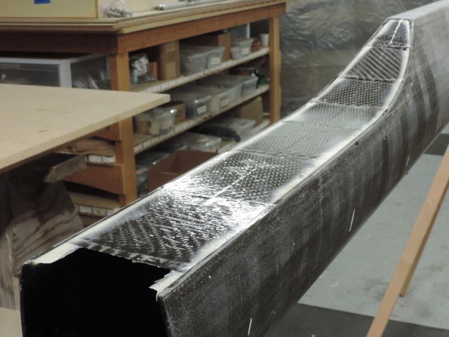
A piece of pre-preg carbon plate (mostly unidirectional) was then bonded to the mast as shown. 

After rounding the edges, a lot of laminate was vacuum bagged over the area using Pro-Set epoxy. This laminating was done in two steps to avoid wrinkling and has fibers running at 0 degrees, 0 - 90, and + - 45 degrees. Note that the lower two inches of the mast will be cut off after this laminating.

The next step was bonding on the new bolt rope track. I bought extruded polycarbonate track from Ted Van Dusen, who runs one of the first carbon spar companies; Composite Engineering. Ted designed this bolt rope track and it has been used it on many masts. 
The first step was to get the track glued on, which would have been easy if I didn't care if it was straight or not. The photo below shows a little jig holding a knife blade that is cutting the green masking tape to the width of the track. This green 3-M tape adheres really well if pressed down hard.

I cut a long strip of wood angled as shown and then cut the strip into little blocks. With the track taped in place using the green tape as a centering guide, the little blocks were glued to the tape every 6" with a little dab of hot-melt glue.

The track was glued on to the mast with West System G-flex, a toughened epoxy that seemed to stick to the polycarbonate track really well (after sanding). Plexus adhesive is usually used for attaching plastic track, but I wanted to use G-flex for the longer working time and because I will be wrapping carbon over the track, making the bond less critical. Plexus fumes are horrible too. 

I wanted to vacuum bag carbon fiber over the whole length of the track to make it reliable, but had to do something to keep the track from pinching under pressure and to keep epoxy from entering the track. A roughly 1/2" x 1/8" stick was milled, covered with plastic tape, and inserted in the track as shown. It protrudes slightly for reasons that will become apparent.

Because G-flex sticks so well to this plastic, the track was primed with G-Flex immediately before applying the wet carbon. This was a thin coat applied with a stiff brush.

The carbon strips were wet out on plastic taped to the bench (using Pro-Set epoxy) and then then applied to the mast. The strips were cut from the end of the roll of 5.7 oz carbon, so were a manageable length. I used three layers for the top half of the mast and two below that, except that both ends had four layers applied.


I forgot to take photos with the bag on, but this is what it looked like after the bag came off. There were vacuum lines coming in from both ends and plenty of breather to allow air flow.

Pushing carbon into inside corners is always challenging because the peel ply and perforated film are not stretchy, which means that they need to be pulled (along with the carbon) toward the inside corner while under vacuum pressure. I used two short lengths of plywood with the ends cut at angles and rounded to push the laminate into the corners from both sides at once as soon as the vacuum pressure started.

After post-curing the laminate with heat blankets, the laminate was block sanded away from the aft face, revealing the spacer. Then the spacer was pried up as shown.


A narrow strip of sail batten was tapered at one end and used with a hammer as a wedge to pry the spacer out in one long piece.


I'm much farther along with all this stuff now, but I'll have to catch up with the blog later. I'll do my best to do blog entries more often. This kind of work is fun for me and the really fun parts are still to come; the new mast head float, carbon hardware, etc...

We still haven't found the right name for the boat. Any ideas?

Happy new year!


Thursday, November 10, 2016

Adventures and a misadventure

Well, I had a great weekend of sailing and one very close call. 
Sailing up to the San Juan’s and back was very educational with lots of different wind strengths from every direction. I went there to sail with boats competing in the Round the County race. It is a two day race completely around the San Juan’s, but I was planning to chase the fleet on Saturday and return home Sunday. 
Photos by Sean Trew

I started well behind the last starters for the beat down Rosario Straight. Despite having to avoid the boats racing, I was able to work my way through quite a bit of the fleet. Near the southern end of Lopez Island, the wind really started to blow.
I had been sailing with the reefed mainsail only, but had to keep reefing it deeper as the wind built. 

The boat was comfortable and felt good despite the conditions getting pretty wild (wind around 25 knots and opposing current causing breaking waves). 
The turning point was a large marker on an exposed reef called Davidson Rock. 

I had over stood the tack and had some room from the reef. Once I was able to crack off onto a reach, I slacked the leeward running backstay and rolled out the jib.
There was a loud bang and the boat capsized very quickly. 

It took a while to get a complete picture of what happened, but it was this: The windward running backstay had let go, allowing the mast to pitch way forward.* The mainsail was the only thing limiting the forward movement of the mast and was pulled very tight as a result. The jib stay went slack causing the jib to be very full, like a spinnaker and the combination of the two (and a gust) caused an immediate capsize.

The amazing thing is that the boat didn’t go upside down, even with the masthead float somewhere out over the bows.

The reef (with breaking waves on it) was just downwind and I didn’t know what had happened to the rig. I thought something had broken, but I got the sails mostly furled and found the running backstays to be in working order. 
I was able to right the boat in a few minutes, get the rig back upright and roll out a bit of jib and ease away from the reef.
photo by Sean Trew
What caused the running backstay to release? The line came out of the cleat. Not because it wasn’t fully cleated, but because the plate that the cleat was mounted to deformed under load and caused the lead angle to the cleat to change enough for the line to pull out of the cleat (see photo below). 
This is new hardware, one size bigger than what came with the boat. It’s a six part tackle with a working load of 900 lbs and a breaking load of 1800 lbs.

The tackle that most G-32’s use has a 600 lb working load (this boat has a tiny rig), so why mine failed is a mystery that I’d like to solve.
I am planning changes to the running back stay system and I’m glad that I now know what happens when when there’s a failure in that system. If it ever happens again, I just hope it’s not near a breaking reef.

Short video  HERE.
Note that the plate that the cleat is attached to is bent
Did I get wet? No I didn't. Only your feet and ankles get wet when righting a G-32. I was wearing an ancient, but well maintained Kokatat drysuit that has kept me dry for almost two decades.

*For those that don’t know, the G-32 has fixed shrouds, but instead of being swept back, they are in line with the mast to allow the mast to raise up and down easily when trailering.

I'm building a new rig for my G-32, which I will post about in this blog. I was planning to make it 3' longer than the stock rig, but that is being reconsidered after my wild weekend.

Text video link if above link fails: https://youtu.be/912H94--Xas


Monday, October 17, 2016

Laminated cross arms for a single outrigger motorboat

This has nothing to do with the G-32, but I just built a set of laminated cross arms for a Bieker designed motorboat that seem worthy of a blog post.


The boat is experimental (don't ask about plans) and the parts for it were cut and built in Port Townsend to be shipped to Bermuda where it will be built.
My job was to cut the lumber kit and build the cross arms and crate all the parts for shipping.

The boat will be 20' long and similar to the single outrigger shown in this video starting at about one minute.  https://www.youtube.com/watch?v=HevgDyupZeY

Solid laminated Douglas Fir was chosen was chosen for economy and strength. The beams took about $ 150 in Fir and took around 25 hours to build to the stage shown.

The weights are 16 lbs for the forward beam and 9 lbs for the aft beam. They will be shaped on the forward edges and covered with fiberglass cloth.
The beams are just under 8 feet long and seem very strong.

The laminates were sawn by bandsaw from three 2"x4"x 9' pieces of Fir. The laminates were run through a thickness planer to remove the saw marks.

I cut these laminates quite thin (around 3/16" to avoid too much spring back at the tightly curved outboard ends, but it still took a lot of force to bend all 11 of the laminates around the jig for the forward beam.  I wanted the laminates to be thin enough to bend to the curve in a fairly relaxed state because I thought that the finished beam would be stronger and the glue-up would be easier.

The obvious solution was to taper the laminates, which turned out to be quite easy using the thickness planer.  I was even able to match the taper to the designed taper of the beams which meant that I didn't have to cut the taper after laminating.

My planer ( a fantastic Dewalt 13" portable) won't plane wood less than 1/4" thick without raising the base with a piece of plywood clamped to it, but with that method I was able to feed laminates into the planer and slowly lower the cutter head until contacting the surface with them about halfway through and then slowly cranking the cutter head down to cut taper before raising it up again and repeating, the second time cranking a bit faster to cut more taper.
I was able to run a couple of laminates side by side and had tapered all the inner laminates before clamping the stack to the gluing jig to check the taper against the CNC cut plywood templates that were provided.
In the end I was tapering one or two laminates at a time in marked areas to achieve the designed taper.


The gluing jigs were made by gluing square-cut block to the bench with dabs of 5-minute epoxy before screwing them to the table. The blocks were aligned to a batten while the 5-minute cured. 
The template would have been used to align the blocks, but I slightly softened the curve near the outboard end to make bending the strips easier.
Plastic tape (visible) was applied to the table before the batten and blocks.


After dry runs and fine-tuning the taper, the beam is ready to glue-up.
Slightly thickened epoxy (105 / 206 with colloidal silica and micro fibers) was applied to both faces of each laminate using a short nap roller that was cut to the width of the strips. The nap roller will apply thickened epoxy much faster and more evenly than a foam roller.


The glue-up was a breeze, partly because the laminate stack could bend so easily, and partly because the jig worked so well.

 I used blocks of wood with long lag bolts to hold the laminate stack down tight to the table surface and used blocks under the head of every clamp to spread the clamping pressure

There was very little spring back when the beam was removed from the jig. I did heat the beam for a full epoxy cure (by tenting with electric heat) before removing clamps.


The aft cross arm is a different dimension and a different curve. The blocks were re-used for the new jig by cutting them down on the table saw.


The beams were run through the thickness planer to clean all the squeezed out epoxy from the fore & aft surfaces (using older blades) before rolling on a thin coat of epoxy for protection.


This photo shows the cross sections at either end of the forward beam. The laminates are quite a bit thinner at the outboard end, except for the outer laminates which were not tapered.